TSxPlus TMR Architecture Overview
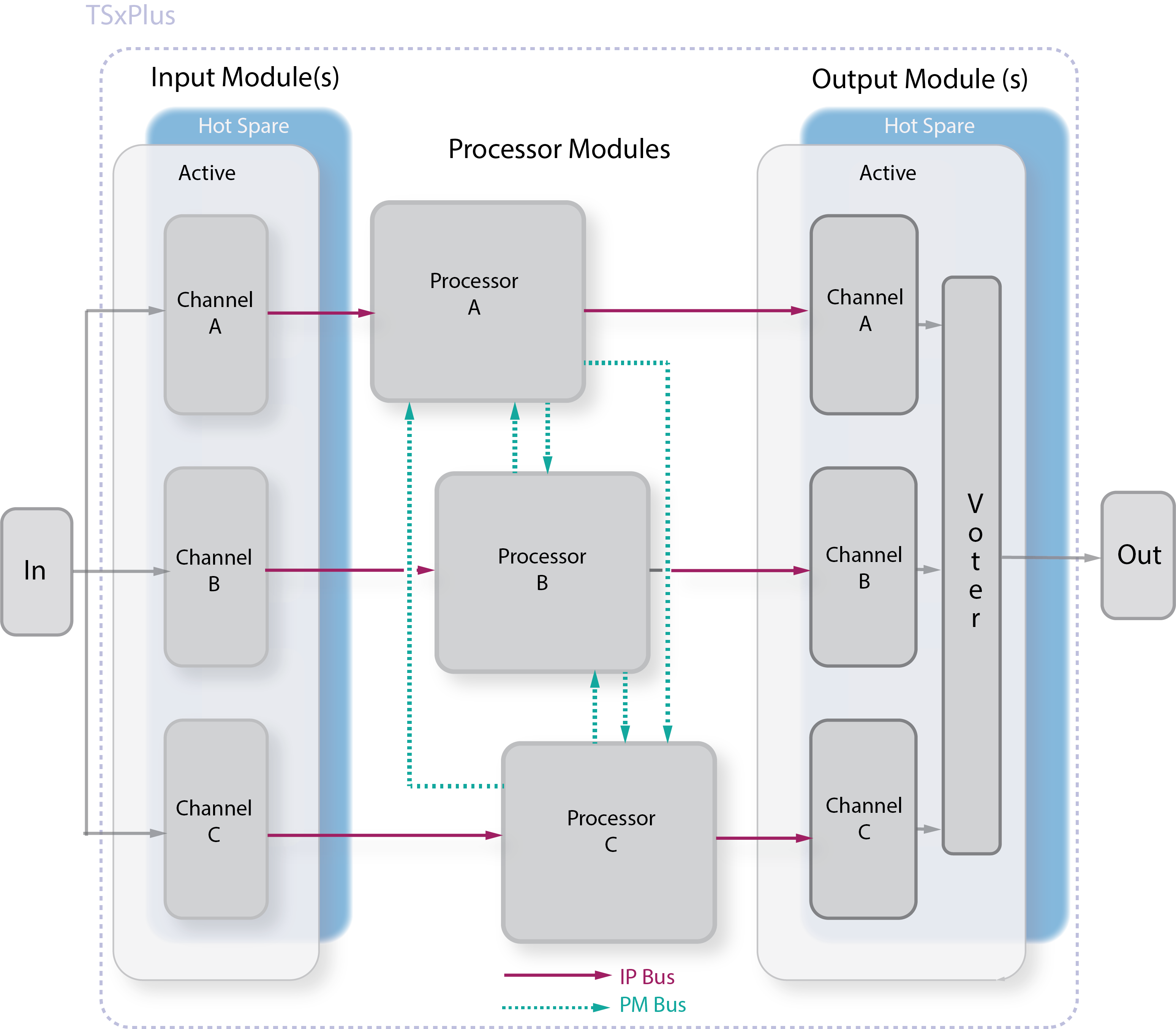
Triple Modular Redundant (TMR) architecture ensures the TSxPlus fault tolerance. It facilitates uninterrupted, error-free control in the presence of either hard failures of components or transient faults from internal or external sources. Each I/O module includes circuitry for three independent channels that interpret and communicate process data using the IP Bus to their respective Main Processor.
The three Processor Modules communicate with each other using a high-speed bus system called the PM Bus. Once per scan, the Processor Modules synchronize and share information with their neighbors over the PM Bus. The PM Bus votes digital input data, compares output data, and sends copies of analog input data to each Processor Module. The Processor Modules take the input data, execute the control program and send outputs to the output modules. The TSxPlus votes the output data on the output modules as close to the field as possible to detect and compensate for errors between the Processor Modules and the final output to the field.
Each I/O slot can contain two identical I/O modules, so control is automatically switched to the healthy module if a fault is detected on one module. A faulty module can also be replaced online (without interrupting the TSxPlus operation) when only one module is installed in the slot. A healthy module is inserted in the spare slot next to the faulted module, and control is automatically switched to this module, which allows the faulty module to be removed from the system.
TSxPlus Processor Modules
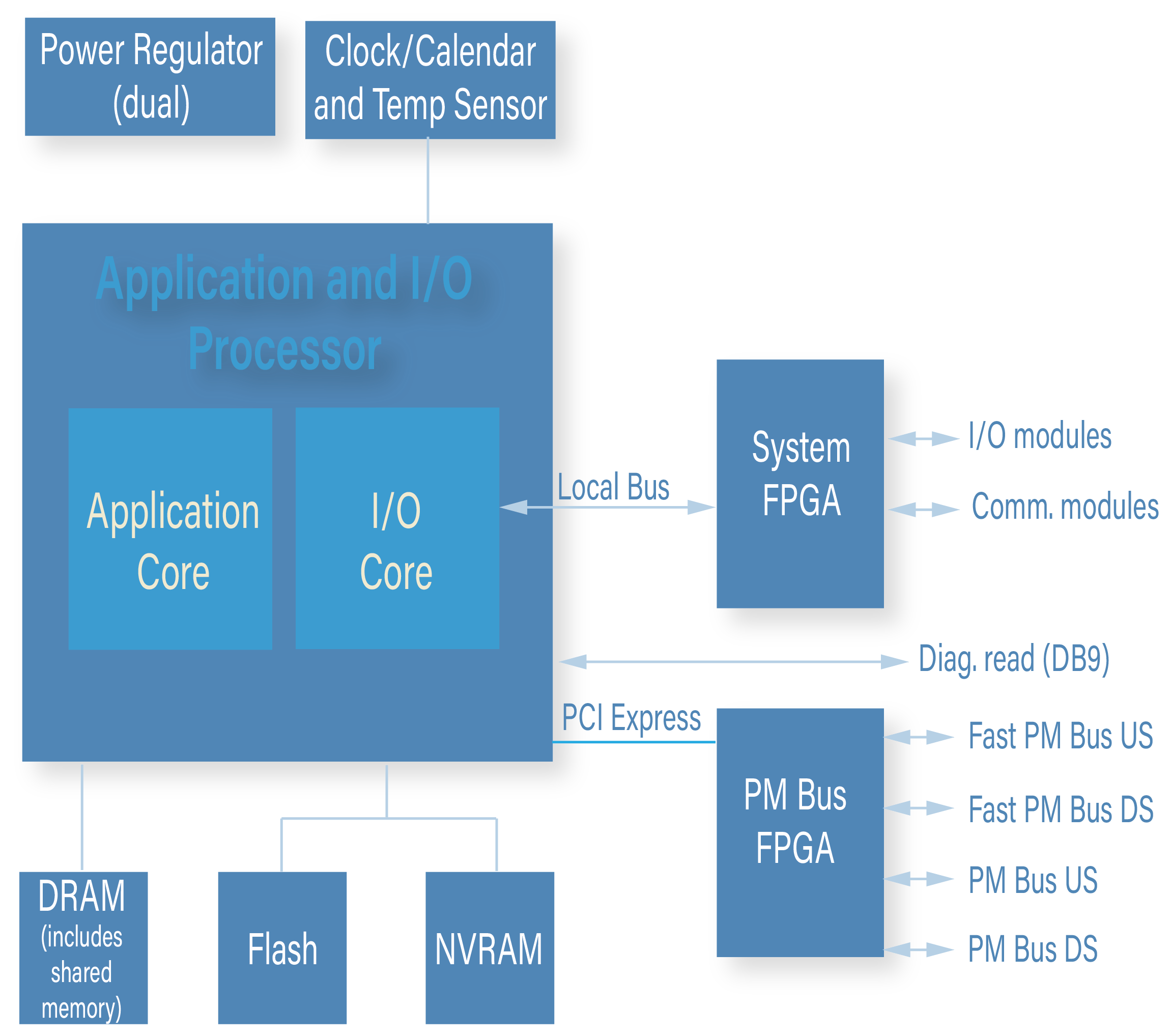
A TSxPlus controller contains three Processor Modules. Each Processor Module controls a separate channel of the system and operates in parallel with the other Processor Modules.
A dedicated I/O Processor on each Processor Module manages the data exchanged between the Processor Module and the I/O modules.
The TSxPlus input data is assembled into a table in the Processor Module and stored in memory for the hardware voting process. The individual input table in each Processor Module is transferred to its neighboring Processor Modules over the PM Bus. During this transfer, hardware voting takes place. The PM Bus uses a direct memory access programmable device to synchronize, transmit, vote, and compare data among the three Processor Modules. If a disagreement occurs, the signal value found in two out of three tables prevails, and the third table is corrected accordingly. One-time differences which result from sample timing variations are distinguished from a pattern of differing data.
Each Processor Module maintains data about necessary corrections in local memory. Any disparity is flagged and used at the end of the scan by the TSxPlus controller's built-in fault analyzer routines to determine whether a fault exists on a particular module.
Using the table of output values, the I/O Core generates smaller tables, each corresponding to an individual output module in the system. Each small table is transmitted to the appropriate channel of the corresponding output module over the IP bus.
PM Bus
The PM Bus consists of three independent serial links which synchronize the Main Processors at the beginning of a scan, and performs either of these functions:
- Transfers I/O, diagnostic, and communication data.
- Compares data and flags disagreements of output or memory data from the previous scan.
An important feature of the TSxPlus architecture is the use of a single transmitter to send data to both the upstream and downstream Processor Modules, which ensures the same data is received by the upstream processor and downstream processor.
IP Bus
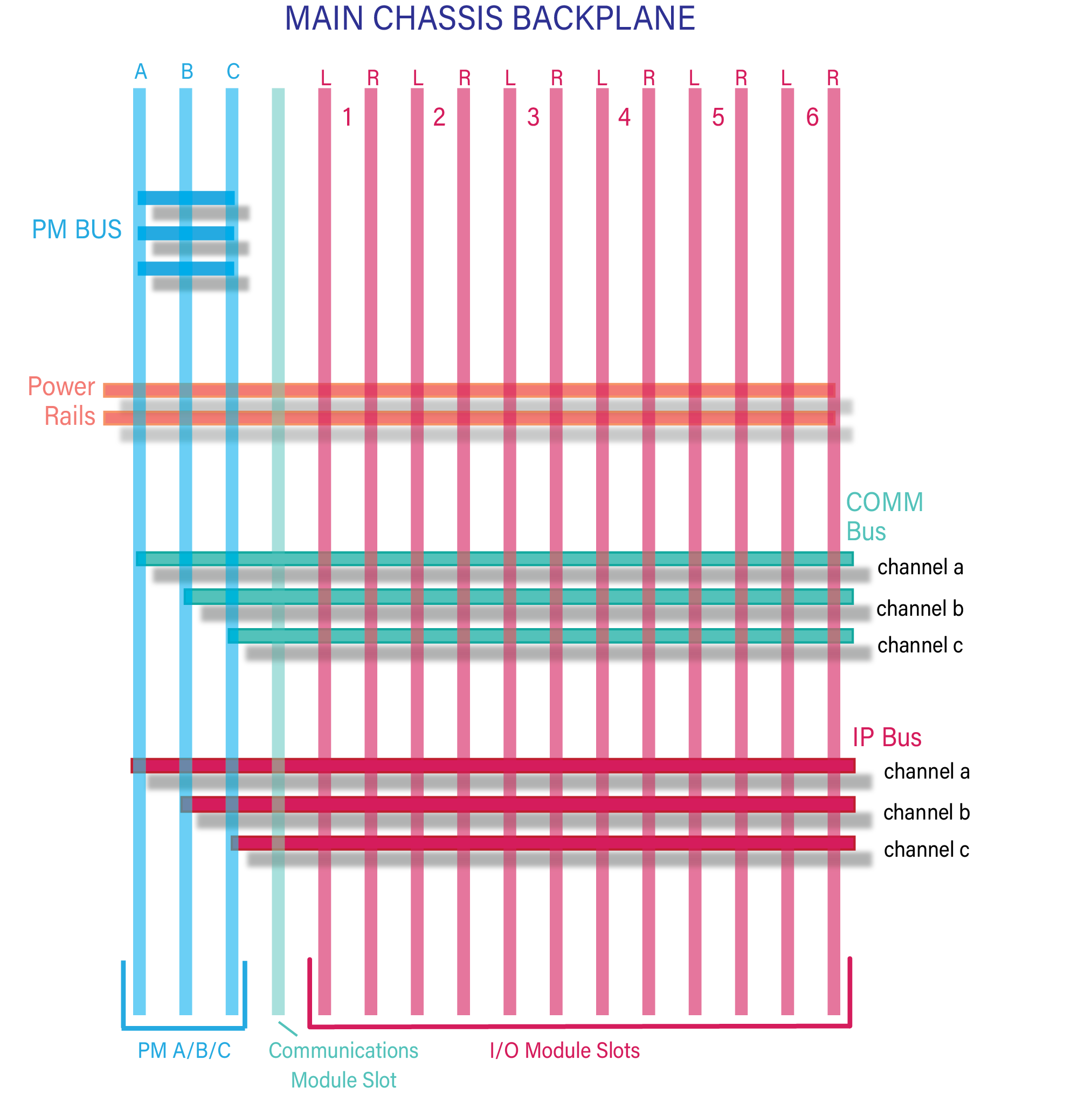
Each I/O module transfers signals to or from the field through its associated field termination assembly. Two positions in the chassis tie together as one logical slot. Termination cables are tied to panel connectors at the top of the backplane. Each connection extends from the termination module to both active and hot-spare I/O modules, which means both the active module and the hot-spare module receive the same information from the field termination wiring.
The triplicated IP bus transfers data between the I/O modules and the Processor Module. The IP bus is carried along the bottom of the backplane. Each channel of the IP bus runs between one Processor Module and the corresponding channels on the I/O module. The IP bus extends between chassis' using a set of three Bus Interface modules and fiber optic cables.
Communications Bus
The communication (COMM) bus runs between the Processor Modules and the communication module(s) at 2 megabits per second.
Power Rails
Power for the chassis is distributed across two independent power rails and down the center of the backplane. Each module in the chassis draws power from both power rails through dual power regulators. There are four sets of power regulators on each input and output board: one set for each channel (A, B, and C) and one set for the status indicators.
Digital Input (DI) Modules
The TSxPlus controller supports two basic types of Digital Input Modules: TMR and Simplex.
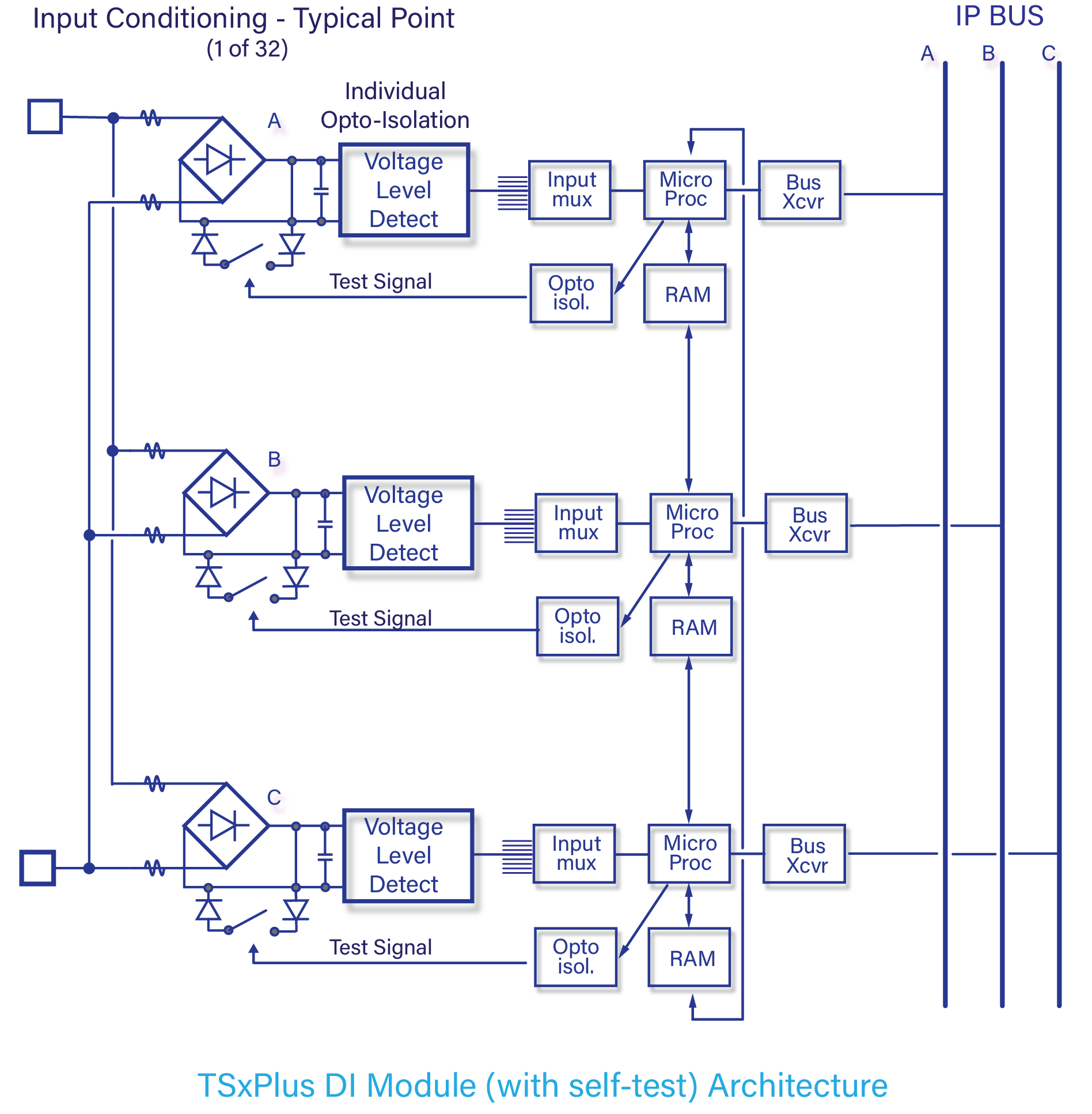
Every Digital Input Module houses the circuitry for three identical channels (A, B, and C). Although the channels reside on the same module, they are entirely isolated from each other and operate independently.
A fault on one channel cannot pass to another. In addition, each channel contains an 8-bit microprocessor called the I/O communication processor, which handles communication with its corresponding Processor Module.
Each of the three input channels asynchronously measures the input signals from each point on the input module, determines the respective states of the input signals, and places the values into input tables A, B, and C, respectively. Each input table is regularly interrogated over the IP bus by the I/O communication processor located on the corresponding Processor Module.
For example, Processor Module A interrogates Input Table A over IP Bus A.
All critical signal paths are 100% triplicated on TMR Digital Input Modules for guaranteed safety and maximum availability.
Digital Output (DO) Modules
There are four basic types of Digital Output Modules: dual, supervised, DC voltage and AC voltage.
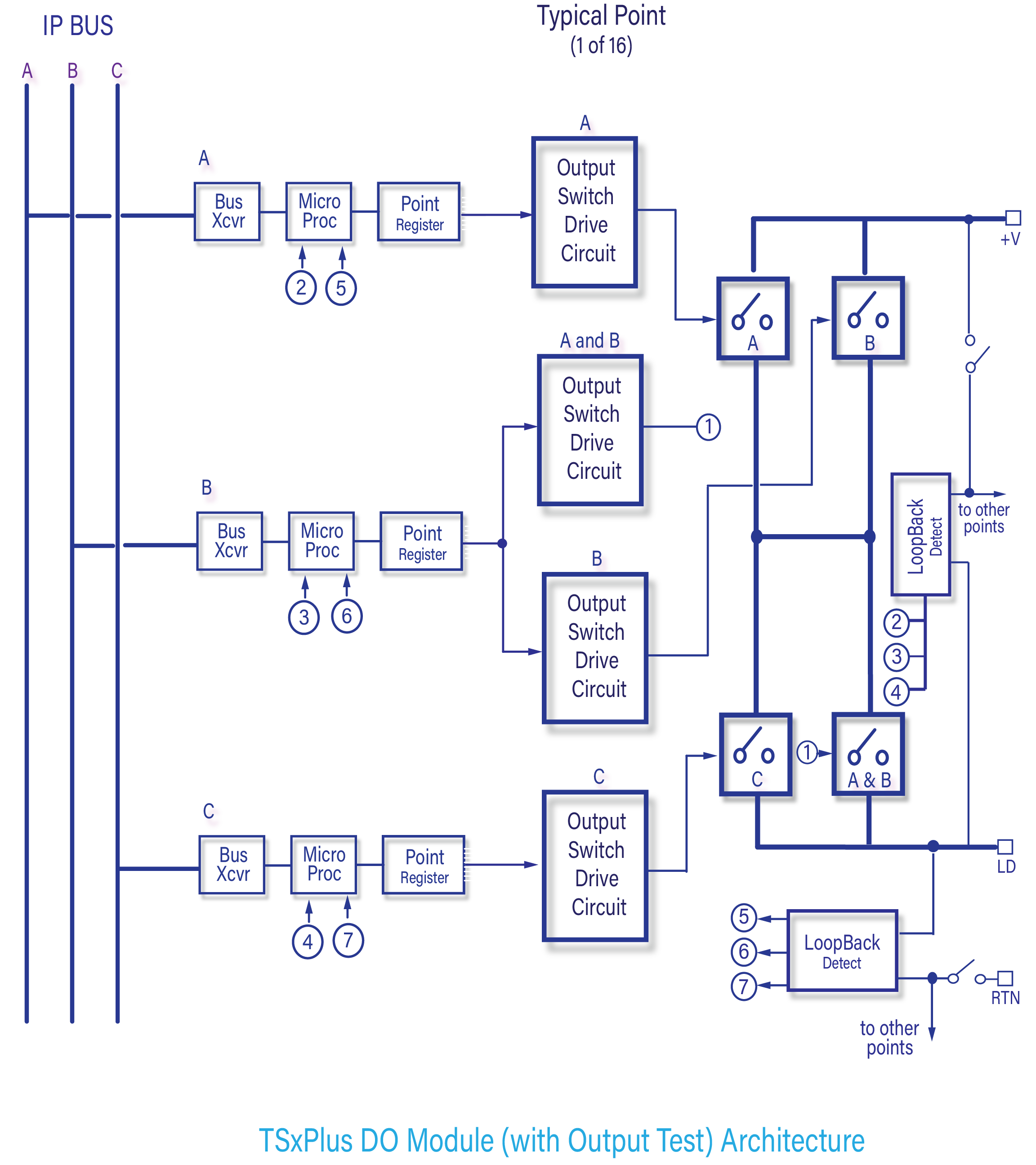
Every Digital Output Module houses the circuitry for three identical, isolated channels. Each channel includes an I/O microprocessor which receives its output table from the I/O communication processor on its corresponding Processor Module.
All of the Digital Output Modules, except the dual DC modules, use a quadruplicated output circuitry, referred to as Quad Voter, which votes on the individual output signals just before they are applied to the load.
This voter circuitry is based on parallel series paths which pass power if the drivers for channels A and B, or channels B and C, or channels A and C command them to close—in other words, 2-out-of-3 drivers voted On. The quadruplicated voter circuitry provides multiple redundancies for all critical signal paths, guaranteeing safety and maximum availability. Each type of Digital Output Module executes a particular Output Voter Diagnostic (OVD) for every point.
Loopback on the module allows each microprocessor to read the output value for the point to determine whether a latent fault
exists within the output circuit
Analog Input (AI) Modules
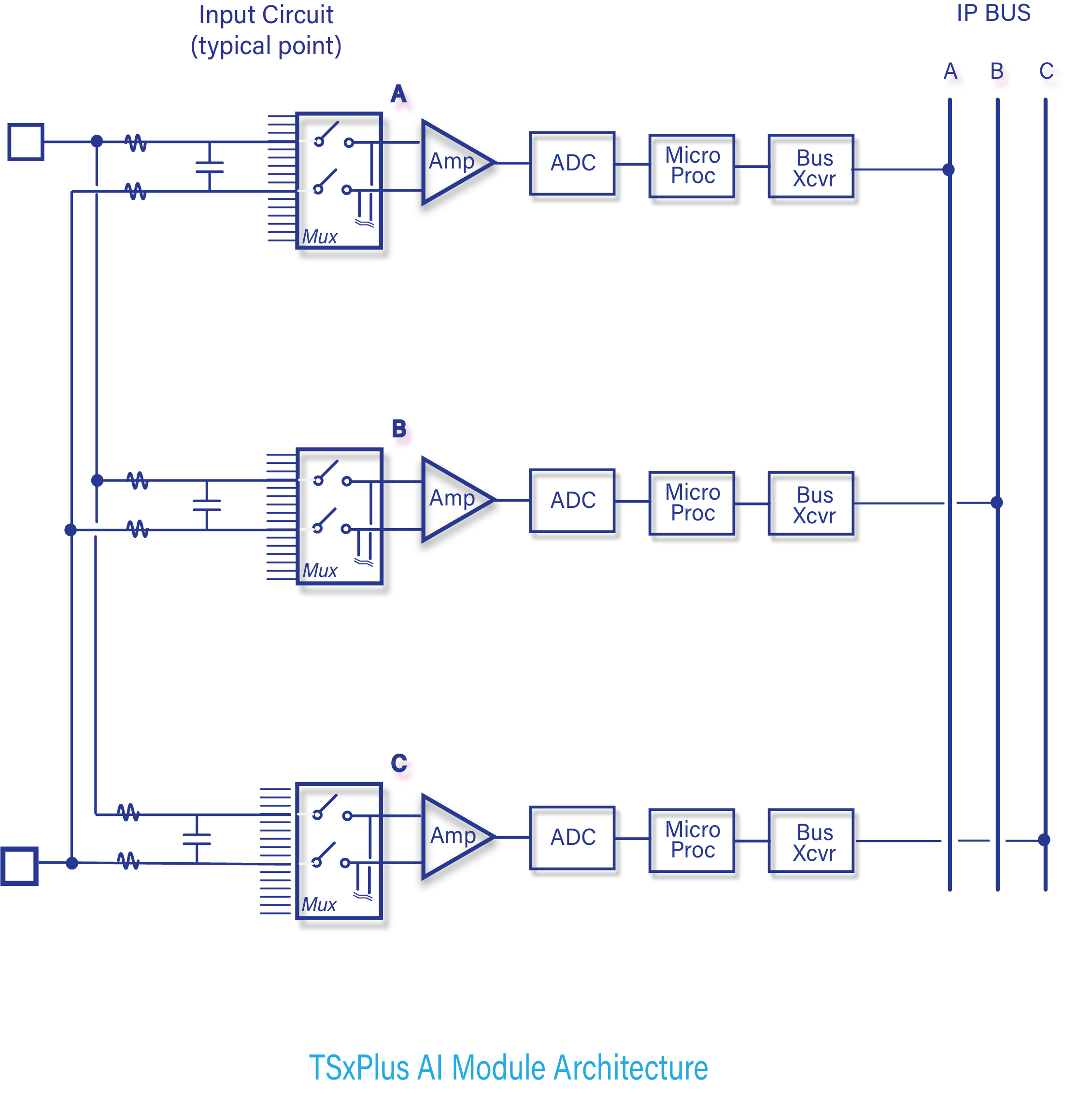
On an Analog Input Module, each of the three channels asynchronously measures the input signals and places the results into a table of values.
Each of the three input tables is passed to its associated Processor Module using the IP bus. The input table in each Processor Module is transferred to its neighbors across the PM Bus. The middle value is selected by each Processor Module, and the input table in each Processor Module is corrected accordingly.
In TMR mode, the mid-value data is used by the control program; in duplex mode, the average is used.
Each Analog Input Module is automatically calibrated using multiple reference voltages read through the multiplexer. These voltages determine the gain and bias that are required to adjust readings of the analog-to-digital converter (ADC).
Analog Input Modules and termination panels are available to support a wide variety of analog inputs in both isolated and non-isolated versions: 0-5 VDC, -5 to +5 VDC, 0-10 VDC, 4-20 mA, thermocouples (types K, J, T, E), and resistive thermal devices (RTDs).
Additionally, the analog input modules support direct connection and protocol analysis of HART-compliant smart instruments.
Analog Output (AO) Modules
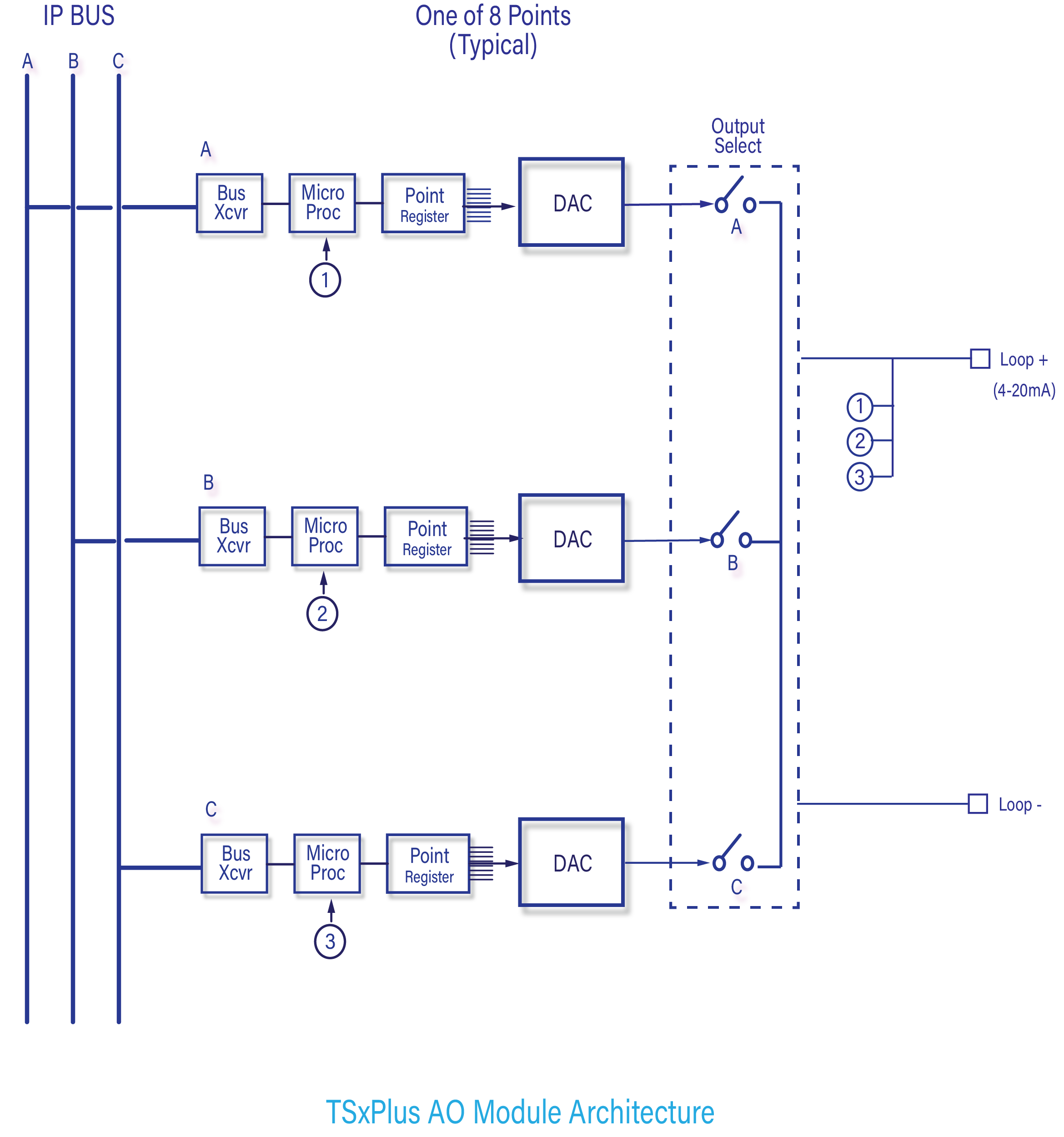
The Analog Output Module receives three tables of output values, one for each channel from the corresponding Processor Module. Each channel has its own digital-to-analog converter (DAC). One of the three channels is selected to drive the analog outputs.
The output is continuously checked for correctness by “loop-back” inputs on each point which are read by all three microprocessors. If a fault occurs in the driving channel, that channel is declared faulty and a new channel is selected to drive the field device. The designation of “driving channel” is rotated among the channels, so that all three channels are tested.
Communications Modules
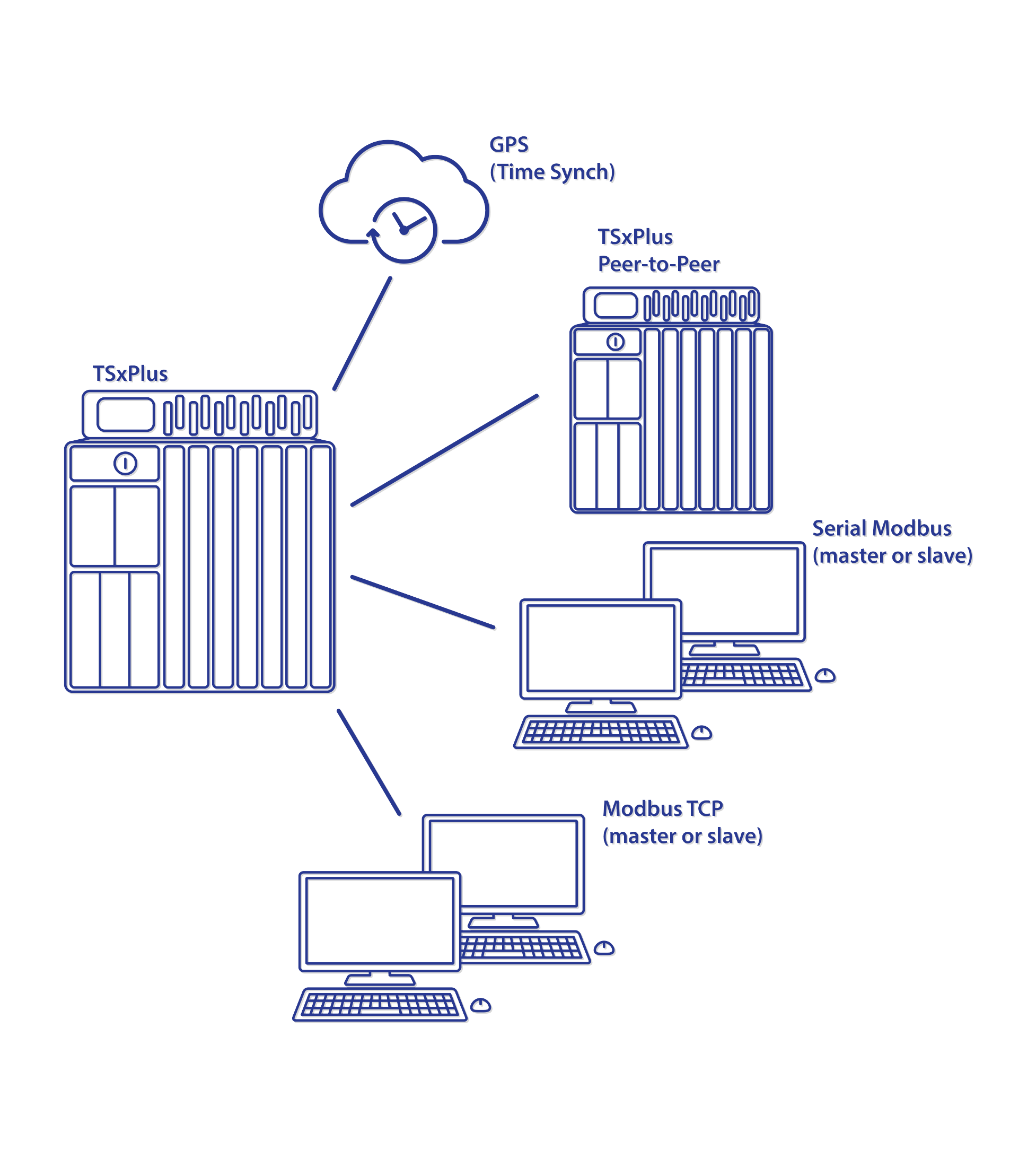
The TSxPlus controller can interface with Modbus masters and slaves (both serial and TCP), other TSxPlus controllers in a TSxPlus Peer-to-Peer network, external hosts on Ethernet networks, including the major DCS platforms including; Yokogawa, Honeywell™ and Foxboro® distributed control systems.
The Processor Modules broadcast data to the communication modules across the communication bus. Data is typically refreshed every scan; is never more than two scan times old.
Speed Measurement and Overspeed Detection/Protection (OSP) Modules
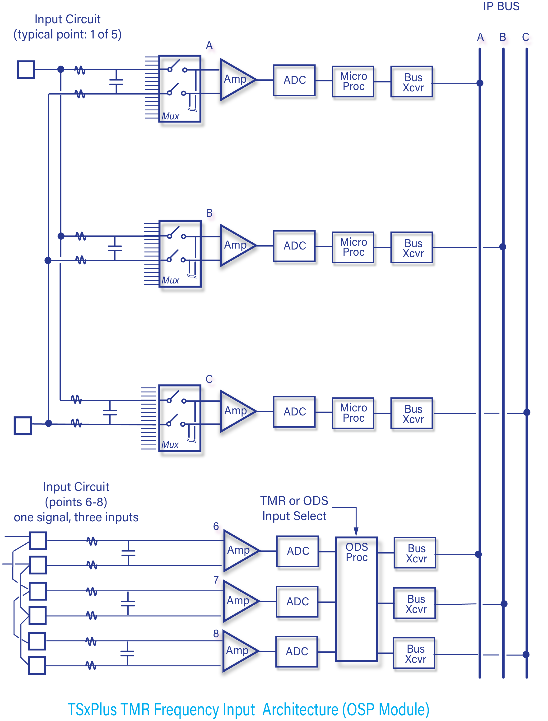
The Overspeed Detection/Protection (OSP) module has eight Frequency Inputs for speed measurement. Five Inputs have triple-modular redundant architecture (TMR), and three inputs can be used either as a Single TMR input or three separate and independent Overspeed Detection inputs. The OSD Module also includes two digital inputs and four digital outputs (related to the Overspeed Detection/Protection function.)
Frequency (Speed) Measurement:
The five TMR frequency inputs function the same as typical TMR inputs with the addition of Frequency signal conditioning and processing.
One frequency input signal is distributed to three channels. Each of the three channels asynchronously measures the input signals and places the results into a table of values.
Each of the three input tables is passed to its associated Processor Module using the IP bus. The input table in each Processor Module is transferred to its neighbors across the PM Bus. The middle value is selected by each Processor Module, and the input table in each Processor Module is corrected accordingly.
When the Overspeed Input channels are used for a TMR input; a single frequency input is connected to the three input channels (jumpering on the field termination assembly). The channel configuration (software) determines if the OSP processor routes the input signal to the IP Bus or to the OSP trip voting circuit.
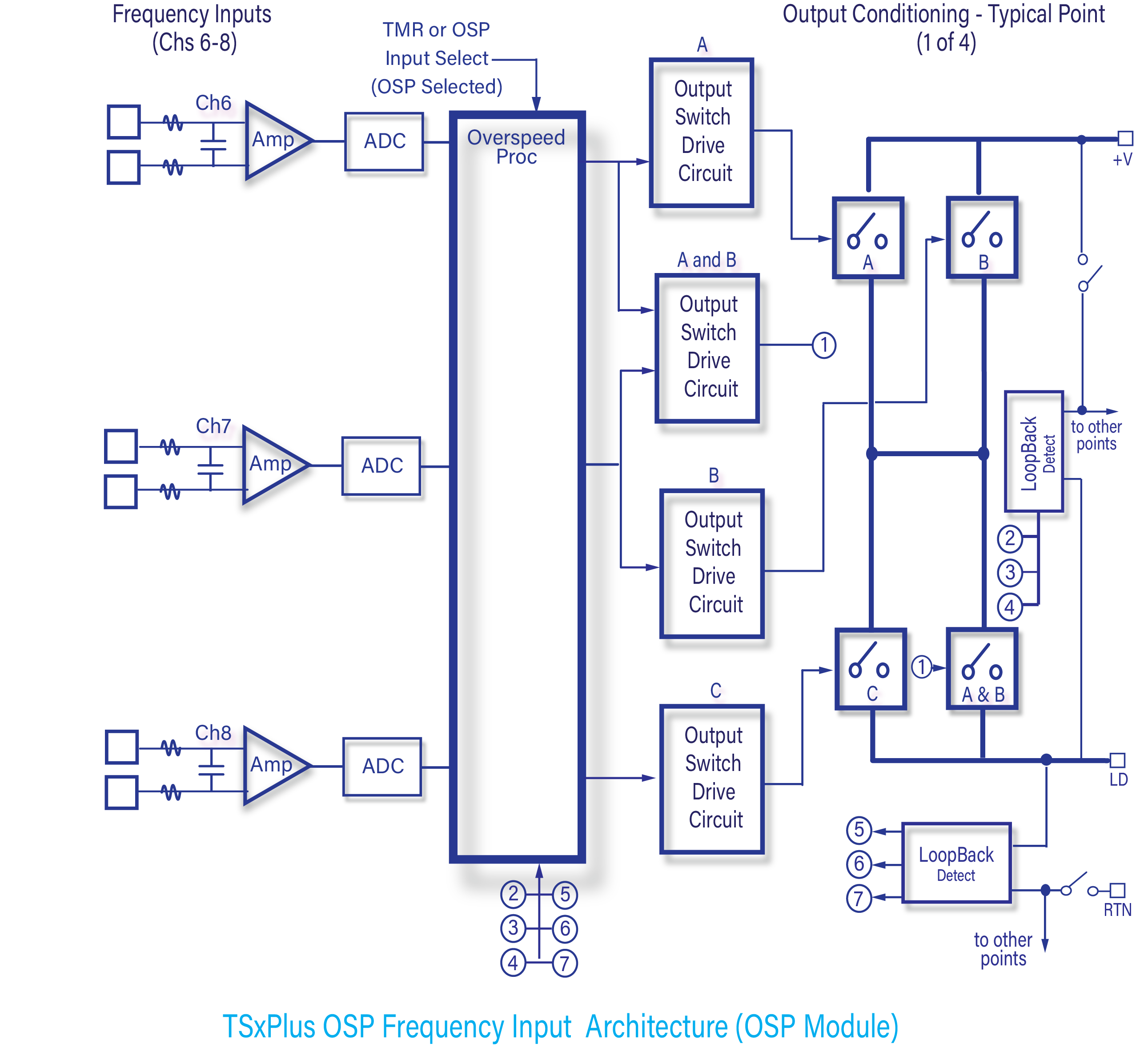
Overspeed Detection/Protection:
The Overspeed Detection/Protection (OSP) function is designed to replace a traditional mechanical trip-bolt on steam or gas turbines, power turbines, and other rotating equipment.
The OSP module provides reliable overspeed trip protection for rotating equipment using up to three (3) speed sensors (dedicated to the OSP function) to determine rotational speed and four (4) digital outputs.
The OSP module independently trips the turbine (de-energizes its four trip outputs) if at least two of the sensors simultaneously detect an overspeed condition.
The Overspeed Detection/Protection module is a SIL 3-rated, triplicated electronic overspeed trip device designed to API612 requirements. It resides in the TSxPlus chassis, and while it has direct communication with the TSxPlus Processor Modules and Communications Modules through their respective busses, it operates entirely independently of the Processor Modules, Communications modules, or the rest of the TSxPlus I/O structure.
Vibration Interface (VPM) modules
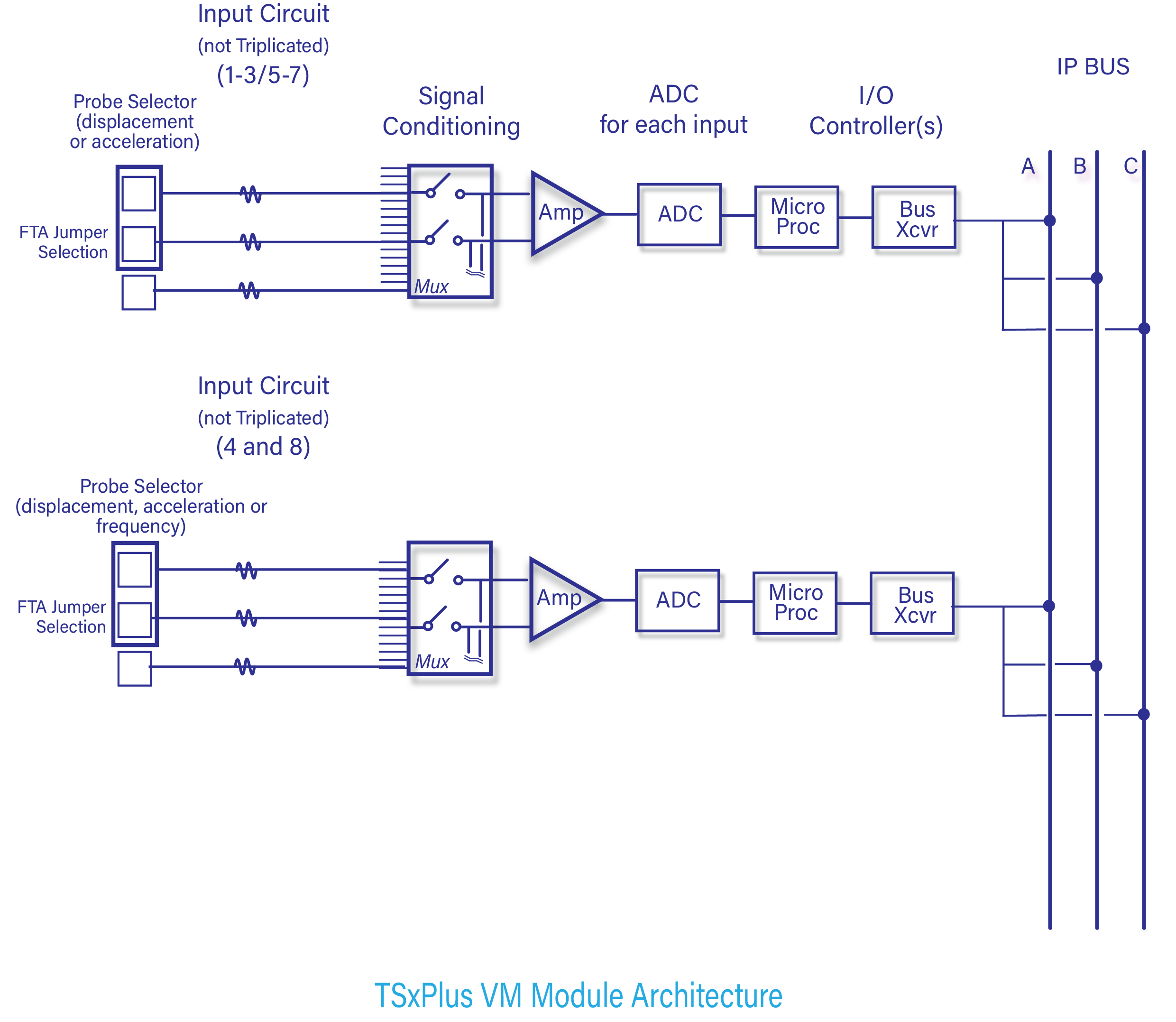
The Vibration Interface module (VPM) continuously monitors eight vibration-related input channels.
The raw vibration input signals are simplex (non-redundant). However, each processed input is communicated to each of the triplicated Processor Modules via the IP Bus interface channels (also triplicated).
Channels one through three of the Vibration Interface module- with its field termination assembly (FTA)- provide configuration-selectable, proximity, or seismic (velocity or acceleration) inputs.
In addition to proximity and seismic input configuration, channels four and eight can interface with magnetic pickups to provide key phasor inputs for shaft speed measurements.
Servo Control and Position Interface (SCP) modules
The Servo Controller and Position Interface module (SCP), when integrated into the TSxPlus rack architecture, is typically used on steam and gas turbine applications to position proportional or integrating hydraulic or pneumatic actuators based on the demand signal from the turbine controller (within the TSxPlus).
The SCP positions the actuator by sending a redundant, configurable position demand to the actuator and senses the actuator position using single or dual-position feedback devices (LVDTs, RVDTs, or DC current).
The triplicated control (process) demand signal input to the SCP is sent from the TSxPlus Processor Modules via the integrated IP Bus.

TSxPlus Standards and Specification Compliance